By following a few rules-of-thumb you can determine the wattage requirement for your application.
Calculating the wattage requirements to heat a system is a straightforward process as long as all the parameters of heat energy flowing in and out of a system are considered. Heat requirements that must be considered are:
Initial heat for the startup of the system, usually from ambient temperature to the desired processing temperature.
Heat losses to the environment due to conduction, convection, and radiation.
Heating of material being processed during operation.
Heating of material flowing through the process such as a liquid that will be heated and pumped to be used elsewhere.
The losses due to phase changes of materials, either during initial heat-up or while processing (melting a solid to a liquid or boiling a liquid to a gas).
Luckily, such precision is usually not required since temperature controllers are commonly employed in most heating applications, meaning that a quick calculation can be used to get you up and running.
Before beginning the calculations, it is important to realize the distinction between energy and power and their relationship to wattage requirements.
In metric units, power is measured in watts (W) and energy is measured in watt-hours (W x hr).
In imperial units, power is measured in British Thermal Units per hour (BTU / hr) and energy is measured in BTUs. A BTU is the amount of energy required to heat 1 pound of water by 1°F (specifically from 39° to 40°F).
Think of power as the rate at which energy is used. A 60 watt light bulb uses 60 watt-hours of energy in one hour.
It also should be noted that the difference between the starting temperature and the desired final application temperature is commonly referred to as delta T (ΔT). If a process is started at room temperature, say 72°F, and the application process temperature is 500°F, then ΔT is 500°F – 72°F, or 428°F.
Below are some good guidelines for heating different materials in different situations.
To calculate the wattage requirement to heat steel, use the following equation:
Watts = 0.05 x Lbs of Steel x ΔT (in °F) / Heat-Up Time (in hrs)
Example: To heat 50 lbs of steel by 250°F in 1 hour; .05 x 50 x 250 / 1 = 625 Watts. Using the same example, reaching temperature in 15 minutes (0.25 hrs); .05 x 50 x 250 / .25 = 2,500 Watts. This equation is suitable for mild and stainless steel. If you are heating a different material than steel, you can replace the 0.05 in the equation above with the following coefficients:
Brass: 0.053
Aluminum: 0.018
Copper: 0.056
To calculate the wattage requirement to heat water in a tank, use the following equation:
Watts = 3.1 x Gallons x ΔT (in °F) / Heat-Up Time (in hrs)
Example: To heat 20 gallons of water by 100°F in 30 mins (0.5 hrs); 3.1 x 20 x 100 / 0.5 = 12,400 Watts
To calculate the wattage requirement to heat flowing water, use the following equation:
Watts = 165 x Gallons Per Minute X ΔT (in °F)
Example: To heat water flowing at 2 gallons per minute by 45°F; 165 x 2 x 45 = 14,850 Watts
To calculate the wattage requirement to heat oil in a tank, use the following equation:
Watts = 1.35 x Gallons x ΔT (in °F) / Heat-Up Time (in hrs)
Example: To heat 5 gallons of oil by 300°F in 15 mins (0.25 hrs); 1.35 x 5 x 300 / 0.25 = 8,100 Watts
There are a variety of other equations that can be used to provide good estimates of the power requirement to heat substances in varying situations. The numbers calculated from these formulas do account for typical losses in most applications and will provide a number that is more than adequate to get your process to temperature in the time required.
For more complicated heating applications, the Tutco engineering team can provide support to help with your calculations and provide solutions for your heating needs.
Sometimes, when all the design work is done, the heating element is too fragile for either the assembly process, or field operation. This can occur when making a low wattage heater that uses a high voltage. In these cases the element needs to be more robust but the design won’t allow it. One solution is to use a diode in series with the heating element. The diode will reduce the applied energy to the heater for any given voltage and allow a larger lower resistance heating element to be used. Naturally, this is not applicable to DC-powered heaters.
How it works:
A diode blocks half of each cycle in the incoming AC voltage wave. This means that there is no power dissipated or applied during those half cycles. So while the applied voltage remains the same as the application requirements, the power reaching the heating element is cut in half. As a result, a larger tougher element with half the resistance is now useable to meet the application wattage.
Engineering Details:
Vrms is the application supply voltage – (Vpk = Vrms * 1.414)
Vrms’ is the volts RMS applied with a diode
W is the application wattage
W’ is the wattage with a diode
R is the originally calculated resistance
R’ is the required resistance to get the same wattage with a diode
Neglecting the .7v diode junction drop for simplicity, we get the following change in voltage applied to the heating element:
So, R’ will have to be half of the original design R to get the same wattage with a diode.
Design notes:
The diode must be able to withstand the peak reverse voltage for the life of the heater. Any diode selected should probably have a Reverse Breakdown Voltage (Vbr) of at least twice the(not the RMS ) of the application voltage. The diode must be able to withstand the peak heater current, for the diode that’s the rated Forward Current or If. Therefore If must be greater than Ipk, where Ipk = Vpk / R’.
Here’s the Catch:
First, once the heater is assembled you can’t check the coil resistance through the diode. If you need to check it you must find a way to test that doesn’t include the diode in the circuit. Second, the calculations shown above seem simple enough but you cannot confirm them with a handheld meter. After contacting a manufacturer of True RMS meters, they verified that no handheld meter will produce accurate readings with half the waveform missing since they cannot do the actual integration of the waveform. So you have to trust the calculations or rely on an oscilloscope to measure the results.
Example:
The photos below illustrate the use of an oscilloscope and the problems with a handheld meter:
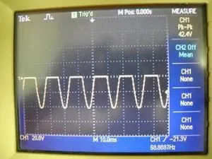
Variac setting showing 30 Vac
Rectified waveform:
Peak voltage shown in upper right (30Vac * 1.414 = 42.4 vac).
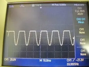
The scope can integrate the waveform to produce an accurate RMS result:
RMS voltage is shown in the upper right
((42.4 – 0.7) / 2) = 20.85
True RMS meter reading Vac and Vdc
The readings are completely inaccurate.
In Conclusion:
While there are certainly some testing difficulties to overcome when using a diode, it is an easy way to make a fragile heating element more robust.
In the heating industry, we are often asked what is the difference between a distributed wattage heater and a zoned heater. These various construction techniques can be applied to many different types of conduction heaters such as cartridge heaters, ceramic and mica strip heaters, and band heaters. Almost any heater that uses a wound coil can use one of these construction methods of controlling watt density. Before beginning, some definitions should be discussed.
Definitions
Coil: A resistance wire (usually Nichrome) that is wound around a round mandrel or ceramic core to hold the shape. When a coil is wound, it is usually done in a uniform manner.
Close Wound: If all the turns of a wound coil touch, this is called a close wound coil.
Open Coil: If the close wound coil is held by its ends and stretched, it becomes an open wound coil. Coils can also be initially wound as open coils if there is space between each turn of the coil.
Pitch: The distance between two turns of an open coil is the pitch.
Watt Density: The wattage produced by a heater divided by the surface area of the heater. Common units of measure are W/in² and W/cm².
Distributed Wattage Heater
What makes a distributed wattage heater? Distributed wattage is when a coil winding’s pitch is not consistent throughout its entire length. Some parts of the winding are more tightly packed with turns than other sections, to “force” the heat profile to be more concentrated in some areas of the heater than another. The non-uniform pitched coil will have sections of closely wound coils and sections of loosely wound coils. These methods of non-uniform stretching or non-uniform winding of the coil pitch allow the heater manufacturer to increase or decrease the watt density of the heater in certain sections. Because the coil winding in some of the sections will be closer together than other sections, the watt density will be greater in those sections. These higher watt density heater sections will be hotter than the other sections. Certain sections of the heater can be now be made to run hotter than other sections. Only one set of power leads is used in this configuration, as the entire heater turns on as one unit.
Application of Distributed Wattage Heaters
A distributed wattage heater allows the end-user to have higher heat where needed. This method of distributing heat is especially beneficial if only a small section of the heater is providing the majority of the heating or in applications where heat is needed over a long length and there tends to be temperature loss or drop-off near the heater ends. Distributed wattage heaters are often used in platens and sealing bar applications where heat loss compensation near the ends of the heater is important.
Zoned Heater
Zoned heating is where a specific section of the heater has its own “dedicated” wound coil with uniform pitch and its own set of power leads for each particular section of a heater. The internal coil construction within this particular type of heater has sections or zones of dedicated uniformly wound coils. The key word in this construction style is “dedicated”. The customer can literally control each section of the heater individually. The heated area is very specific and controllable. For example, a 2-zone heater will have 4 power leads coming out of it; a pair of leads for each zone. Sometimes a common wire may be used; in this 2-zone example, the number of leads can be reduced because each zoned coil shares a common lead. A heater like this would have 3 power leads.
Application of Zoned Wattage Heater
Zoned heaters can be used in any application distributed wattage heaters are used but in most cases, this would probably be overkill and not justify the added expense of the zoned heater. Zoned heaters are best used in applications requiring a significant level of heat control over the length of the heater. Zoned cartridge heaters can have various sections literally turned off entirely while only a fraction of the entire heater is energized. These heaters are commonly used in heater bar applications where heat control at precise locations is an important factor.
As the name implies, duct heaters are generally designed to be installed into ducting. They are usually installed through the side wall to cause the air in the duct to be heated as it flows around and through the open-coil elements.
Duct heaters made by TUTCO-Farnam are not for HVAC use. They are for industrial type applications and are not built to the standards required for the typical residential HVAC. For HVAC applications go to www.tutco.com/duct-heaters/.
Sizes and Shapes
At TUTCO-Farnam the standard shape is square, but rectangular duct heaters are common as custom-built units. Round duct heaters are also possible for unique applications.
Our pre-designed square duct heaters are offered in 6”, 12”, 22” & 36” sizes.
Circuit Types
Single-phase and three-phase duct heaters are available in voltages up to 600V.
We make individual duct heaters from less than 1kW up to 75kW.
A duct heater may be configured in stages, if desired. Each stage is a ‘stand-alone’ circuit. Multiple stages may be used for different reasons via a dual controller, if desired.
Each stage may be powered up separately to achieve various levels of heat output.
Each stage may be wired independently to minimize the amp load, which allows smaller gauge cables. They may still be operated in unison.
Watt Density
Watt Density of the heater coil is the watts per square inch of the surface area of the coil wire.
Watt density is not normally specified by the user, however, one may specify a ‘not to exceed’ limit on the watt density. Watt density can range as high as 90 W/In² but lower numbers are preferred. A watt density of 50 W/In² is very conservative. Generally, the life of the coil is shortened as the watt density increases.
Min/Max Flow Rates
The minimum and maximum flow rates are calculations based on the velocity of the air and the area of the duct.
We suggest a minimum of 200 fpm of air flow, but more is better, if possible. Without adequate airflow most duct heaters are apt to fail due to coil overheating and result in breakage.
The airflow is required to keep the coils from overheating.
We suggest a maximum of 7000 fpm of air flow, primarily to avoid deflection of the coils due to the ‘wind resistance’. Of course, a light gauge coil is much more susceptible to deflection than a heavy gauge coil would be. Light gauge coils are avoided whenever possible for this reason.
Installation Concerns
The primary concern with installation of a duct heater is the orientation of the heater with respect to the axis of the coils. The coil axis must be horizontal. That means the termination plate (face, or front) of the heater is mounted to a vertical side of the duct.
Horizontal mounting assures the coils are adequately supported by the ceramic bushings. If the heater were to be mounted vertically, the coils could sag down to the point of shorting the coil wraps together. They could also drop out of the “bottom” bushing and short to the ducting.
Should the application require multiple heaters, avoid mounting them closely side-by-side. Instead, leave at least a few inches between them. This allows the air to mix or blend before it encounters the next bank of heater coils.
When a thermocouple is to be mounted downstream, it should be mounted away from the heater for the same reasons as above. Thermocouples should also be long enough to reach well into the duct, away from the less-mixed (and cooler) air near the walls.
Summary
Your TUTCO-Farnam duct heater will have a long life when it’s properly installed and operated.
Thermodynamics, specifically heat transfer, is used throughout our daily lives, but not always thought of. A common practice of cooking breakfast would be one simple example. You place one type of media, your frying pan, onto a hot surface and apply the “heat”, which is your source of energy, to cook the food. The heat transfer that is occurring between the higher temperature stove-top and the cooler frying pan is a great practical application. It is also a simple example of the second law of thermodynamics, “Heat cannot, of itself, pass from a lower temperature to a higher temperature.” Thus, for heat transfer to occur, we can state that a temperature difference must exist between two mediums.
As we further study heat transfer and any thermal system, we will need to consider the three types of heat transfer, which are conduction, convection, and radiation. In many cases, you can have two or even all three sources of heat transfer happening simultaneously. As each form of heat transfer is briefly discussed I will list an example in the following paragraphs.
In order to fully understand how conduction, convection, and radiation are affected, you must consider the rate at which a certain medium will affect your system design. The rate at which energy or heat is absorbed or dissipated is dictated by the thermal conductivity of a material or combination of materials, temperature difference, area of the surfaces, and mass of the combined components. By varying the previously mentioned attributes, one can increase or decrease the speed and efficiency of a thermal system.
Now let’s look at a short study of each type of heat transfer. The first form is conduction. Conduction is a thermal process that occurs between two surfaces in contact with each other, where a temperature gradient exists, or even in one material that has a temperature gradient between two planes. If we use a simple experiment of a uniform bar of cross-section A, perfectly insulated on all sides except at the ends; where heat can only flow in the ‘x’ direction (see Fig. 1). If the bar is maintained at t1 on one end and t2 at the other end, Q (BTU/Hr (BTU = British Thermal Units, HR = Hours) will be transferred steadily from the entry, at location 1 to the exit at location 2. The rate of heat flow (heat flux) is directly proportional to the cross-sectional area and temperature difference from point to point of the bar. You may want to compare the cross-sectional relationship of the bar to how water flows through a pipe. The larger diameter of the pipe, the more flow of water (energy) it can transfer. If we now determine how the length of the bar will affect the heat transfer rate, we double the length (2L). It is found that the heat transfer rate is cut in half, which demonstrates that the heat transfer is inversely proportional to the length of the bar.
Fig. 1
Equation 1 shows mathematically the relationship of all the factors, where the proportionality constant, k, is a property of the material called thermal conductivity. The negative sign has been included in equation 1 to indicate a positive heat flow. The conductivity, k, is usually a function of temperature, but for moderate temperatures and temperature differences, it can be considered a constant.
Equation 1: Reference bibliography
Example: A plane wall constructed of solid iron with thermal conductivity 70 W/m°C, thickness 50 mm and with surface area 1 m by 1 m, temperature 150°C on one side and 80°C on the other.
The second form of heat transfer is convection. Convection is the transfer of heat through the motion of a liquid or gas relative to the body of material. There are two types of convection, forced convection, and natural convection. If the motion of the fluid is caused by the different densities initiated by the different temperatures in various locations of a fluid, it is known as natural convection. If the motion of the fluid is caused by an external force, such as a fan or blower in air heating then it is considered forced convection. With natural convection, the minor temperature differences in a fluid can cause heat transfer. For example, a room in your house could have small temperature differences from an outside wall to an interior wall. Those hot and cold particles coming into contact with the wall will collide and cause a transfer of energy. The equation for Newton’s law of cooling helps explain how basic convection is mathematically represented (see Equation 2). It is much more in-depth to explain forced convection, so that could be covered in future articles.
Equation 2: Reference Bibliography
Q = heat-transfer rate (BTU/hr)
A = heat-transfer area (FT2)
∆T = temperature difference between the surface and the bulk of the fluid away from the surface (°F)
h = coefficient of heat transfer (BTU/hr – ft² – °F)
Example: Fluid flows over a plane surface 1 m by 1 m with a bulk temperature of 50°C. The temperature of the surface is 20°C. The convective heat transfer coefficient is 2,000 W/m2°C.
The third and final form of heat transfer is radiation. Radiant heat transfer differs from the other forms. Radiation does not require any medium to transfer heat. Radiant heat transfer is similar to the “electromagnetic phenomenon” similar to light, x-rays, and radio waves. In this case, a transfer of heat occurs when the absorption of energy is greater than what is radiating from the same body. A body that absorbs all radiation and does not radiate any heat energy itself is considered a “blackbody.” The small amount of heat that is reflected is considered the body’s reflectivity, the amount of heat absorbed is known as absorptivity, and the effectiveness of as a thermal radiator is known as emissivity. The radiant heat transfer rate is shown in equation 4.
Equation 4
σ = Stefan-Boltzmann constant = 0.173 x 10 – 8 BTU/hr – ft2 – °R4 (in SI – 5.669 x 10⁻⁸ Watts/m2 – °K4)
Fe = emissivity factor
FA = Geometric factor to allow for the average solid angle through which one surface “sees” the other
Example: Radiation from the surface of the Sun If the surface temperature of the sun is 5800 K and if we assume that the sun can be regarded as a black body the radiation energy per unit time can be expressed by modifying (1) like
q / A = σ T4
= 5.6703 10-8 (W/m2K4) (5800 (K))4
= 6.42 107 (W/m2)
All three of the previously mentioned heat transfer factors must be considered when sizing a heater for any application. If a band, cartridge, or a strip heater, is selected, all of these elements work on the same design principles. The system can be insulated to improve efficiency during operation and controlled to more accurately provide heat. The final power requirements and efficiencies will depend on a well-designed system that eliminates heat loss and offers close control. A good rule of thumb, after the initial requirements are determined, that a designer uses a 25% service factor or a 1.25 multiplier for the wattage output of the system.
Bibliography Equation 1, 2, 3 and Table 1 from “Thermodynamics and Heat Power”, Sixth Edition by Irving Granet and Maurice Bluestein, Copywrite 2000, Published by Prentice-Hall, Inc., Upper Saddle River, New Jersey 07458
Footnotes 1 See page 581, from “Thermodynamics and Heat Power”, Sixth Edition by Irving Granet and Maurice Bluestein, Copy-write 2000, Published by Prentice-Hall, Inc., Upper Saddle River, New Jersey 07458
When designing an electric heating system for industrial processes, many factors must be addressed. These factors routinely include required power, location, ducting, air source, and controls, but circuit protection is often overlooked. Proper circuit protection is of utmost importance not only for safety but also to avoid costly downtime and repairs to the system. Electrical branch type and size of protection are important considerations when adding circuit protection to a heating system. Depending on the type of controls employed, the speed of operation can also be a factor.
There are two common primary types of overcurrent circuit protection: circuit breakers and fuses. The type of protection required depends on the type of control system used. A simple convection heater system, using only a heater and blower or fan, can be effectively protected with a circuit breaker. However, more complicated systems that add controls tend to need more complex protection.
Proper sizing of the circuit protection is the first step. The current value of the protection should be 125% of the maximum continuous amperage drawn on the circuit. This sizing will eliminate any false tripping or open fuses in the system.
Example: A heater rated for 10kW at 480V 3PH is being installed in a drying system. The heater will be operated at full power with no control over its output. It will be coupled with a 6 HP regenerative blower in the same circuit that is rated for an airflow of 200 CFM at 5.2A maximum load at 480V 3PH 60Hz. What size circuit breaker or fuse would be adequate for branch circuit protection of this system?
First, let’s find the line current on the heater:
Where: A = Line Current, W = Total Heater Wattage, V = Line Volts
Since the blower is rated at 5.2A, the continuous load of this circuit is 17.2A. 125% of 17.2A is 21.5A and so this circuit will require a 25A common trip circuit breaker. If the load is a delta circuit, a three-pole circuit breaker should suffice. However, if the load has a neutral connection, then a four-pole circuit breaker should be employed to ensure a positive disconnect of the neutral wire.
If the above heater system included a temperature controller to regulate the power to the heater, it would be wise to verify the means employed to fire the power circuit. In most modern heater controls, a PID temperature controller receives feedback from a temperature sensor at the exhaust end of the heater. This temperature controller then produces a control output that turns a solid-state device on and off depending on the control state. The solid-state device then delivers power to the heater.
Solid-state devices for heater applications generally are either a silicon-controlled rectifier (SCR) or a solid-state relay (SSR). Both of these devices are effective at handling the power loads required in a heater circuit. Although these devices are ruggedized for industrial applications, they are very sensitive to overcurrent and short circuit conditions. Since they tend to fail closed, it is extremely important to ensure they are protected.
There are several types of overcurrent protection devices on the market targeting semiconductors. When protecting these types of devices, the first step should be to determine the I2T rating requirement of the semiconductor. I2T is the amount of energy required to clear the electrical fault. Generally, a circuit breaker will not react quickly enough to save the semiconductor device and should be avoided. There are two types of semiconductor fuses on the market; gR-type and aR-type. The aR-type fuse is most suitable for this type of application since they are faster acting than the gR-type fuses. The aR-type fuse is often labeled as ultra-fast or ultra-rapid. Each wire in the branch circuit supplying the temperature controller should have an aR-type fuse installed. Calculations for sizing of the protection devices are the same as provided in the previous example.
Although this information has been carefully considered, always consult local and national electric codes when installing new electrical equipment.
Once process equipment is designed and placed into service, the importance of each individual component is frequently forgotten. Unfortunately, heaters often find themselves in this situation until there is a failure. Since heaters usually play an integral role within the application, any failure can rapidly expand to a major issue or shutdown. The good news…many of these disasters can be avoided by increasing the mean time between failures!
Let’s discuss how heaters fail and what can be done to maximize their service life.
During normal heater usage, nickel-chrome (NiCr) alloys form a protective chromium oxide (Cr2O3) layer when heated to 800-900°C in the presence of air. The oxide layer is relatively thick and greenish in color and has a tendency to flake off during thermal cycling. This flaking exposes the base metal to further oxidation, eventually leading to element failure when the chrome is depleted.
At temperatures above 1000°C, Iron-chrome-aluminum (FeCrAl) alloys form an oxide comprised mainly of alumina (Al2O3). Like chromium oxide, an iron-chrome-aluminum oxide is very stable. However, it has one very important difference. It is very thin and adheres very well to the base metal, making it less likely to flake off and lead to product contamination. As the element is thermally cycled, small cracks may develop in the oxide, which eventually will lead to aluminum depletion in the base metal.
Below the temperatures mentioned above, the oxide layers are quite complex but less conducive to preventing heater failure. In general, all resistance heating alloys have a practically unlimited life below 600°C provided they are not exposed to any chemically, mechanically, or electrically damaging conditions.
Although resistive alloy heaters are inherently self-destructive, there are many practices that will aid in preventing a premature heater failure.
Contamination is a frequent cause of heater failure. Do not expose elements to any liquids, conductive or nonconductive solids, or contaminating gases. Always ensure your heater supply air is clean and contains no moisture or lubrication. Also keep in mind when not in use, many processes allow product and/or byproduct to flow upstream and contaminate the heater from the exhaust end.
Excessive temperature cycling is very detrimental to the life of a heater. The most detrimental is the cycle rate that allows full expansion and contraction of the heater resistance alloy. A heater’s wattage should be matched as closely as possible to the application’s actual load requirements to limit thermal cycling. The problem with cycling is the oxide will either crack or spall off exposing the base material to further oxidation and eventual failure. The most effective way to minimize heater element temperature cycling is to use a process thermal controller. A solid-state relay and PID temperature controller combination provides the best performance for both the thermal system as well as for the heater itself. Solid-state switching devices cycle power to the heater very rapidly. This fast-power cycling dramatically reduces heater element wire temperature excursions and substantially extends heater life.
Just as the expansion and contraction of thermal cycling will damage the oxide layer, excessive movement and vibration can be equally destructive. During high levels of movement and vibration, the element may contact conductive or nonconductive structures and supports within the heater assembly. Contact with conductive objects may lead to instant failure by ground short. Contact to nonconductive objects may physically damage the oxide layer and may even damage base metal structure under extreme conditions. It is best to isolate the heater from as much movement and vibration as possible to prevent this type of damage.
It is essential to ensure a heater’s rated voltage matches the supply voltage. Heater wattage increases with the square of the increase in voltage applied. This will negatively impact heater life by significantly raising element operating temperatures.
Perhaps the most important practice is to properly design the process around the heater. Ensure controls are in place to prevent heater failures caused by system failures. Use flow sensing devices to prevent heater operation during periods of insufficient airflow. Devices to monitor process air or heating element temperatures should also be incorporated to ensure temperatures cannot exceed established threshold limits. The use of these types of devices can nearly eliminate the possibility of immediate heater failure during an outside-of-normal system operating condition.
These are only a few examples of conditions that can significantly reduce the life of a heater system. Take time to evaluate your system to ensure you avoid premature heater failure.
The majority of TUTCO–Farnam Custom Product’s heaters are used to heat an air flow. When determining the power required to heat a stream of air, invariably two questions will come up.
How much “stuff” do we have to heat up? In more technical terms, what is the mass flow rate?
How hot does the air have to get? In other words, what is the temperature rise required?
We are going to concentrate on the first question. In the US, it is very common to see the volumetric air flow rate stated in units of Cubic Feet per Minute. Whether it is supplied by a fan, blower, or compressed air line, the volumetric air flow rate is simply stating the volume of air passing through over a given unit of time. SCFM is an acronym for Standard Cubic Feet per Minute, with “Standard” implying standard conditions. For the sake of this discussion, we are going to assume standard conditions of 1 atm and 68°F. Different industries and standard organizations actually cite slightly different values for what standard conditions are, but we are going to save that discussion for another time.
Cubic Feet per Minute = CFM = ft.3/minute at actual conditions
Standard Cubic Feet per Minute = SCFM = ft.3/minute at standard conditions (1 atm = 14.7psi, 68°F )
Why do that?
A volumetric flow rate with units of CFM implies that the flow rate was measured at actual conditions (actual pressure, actual temperature). The distinction between SCFM and CFM is important because air density will change with pressure and temperature. This can be seen from taking a look at the ideal gas law. As you may remember, density = mass/volume. When the ideal gas law is rearranged, the air density can be seen to be proportional to pressure, and inversely proportional to temperature.
PV = mRT → ρ = m/V = P/RT
Air density at standard conditions = .0752 lb./ft3
Since the air density of an air flow stated at standard conditions (SCFM) is always the same, it is essentially a mass flow rate! Stating an air flow in units of SCFM makes it easy to compare conditions, and certain calculations simpler.
ρ = m/V → m = ρV →m/t = ρ (V/t)
mass flow rate = density* Volumetric flow rate
How do I convert to SCFM?
We can easily derive the conversion equation from the ideal gas law and the mass flow rate equation above. The mass flow rate is equal whether the flow is stated in CFM or SCFM.
Note: The ideal gas law uses absolute pressures and an absolute temperature scale.
SCFM = CFM * (Pactual/14.7psi)*(528°R/Tactual)
Let’s put it to use
Case 1
We need to heat up an air flow of 25 CFM at a pressure of 30 psig, and 90°F up to 200°F.
Convert flow to SCFM:
30 psig = 44.7 psia, 90°F = 550°R
SCFM = (25)*(44.7/14.7)*(528/550) = 73 SCFM
The equation Q/t = (m/t)*cp*ΔT can be approximated for air to:
Power [Watts] = (1/3)*SCFM*ΔT [°F]
Power [Watts] = (1/3)*73 SCFM* (200°F – 90°F) = 2676W
If we assume 15% more power for various losses, 3100W will be required.
Case 2
We need to heat up an air flow of 200 CFM from 60°F up to 200°F using a blower operating at a static pressure of 2 in.H2O.
Convert flow to SCFM:
2 in.H2O = .072 psi = 14.772psia, 60°F = 520°R
SCFM = (200)*(14.772/14.7)*(528/520) = 204 SCFM
Power [Watts] = (1/3)*204 SCFM* (200°F – 60°F) = 9520W
If we assume 15% more power for various losses, 11kW will be required.
Conclusion
For Case 1, if we had merely plugged in 25CFM into the above equation, we would have been undersized by a factor of about three. For Case 2, if we would have used 200CFM, we would have been under by 2% if we had not converted to SCFM.
Grounding in General Grounding is often treated as an afterthought, but not all grounds or ground connections are the same. Too often we just assume that any ground connection will be a ‘good’ one. Grounding a device generally serves two purposes. The first is to provide a safe path for current flow in the event of a short circuit. The second is to provide a true “zero voltage” reference for the circuit.
Grounding a Heater for Safety To protect against any kind of insulation failure within a heater, exposed metal parts are connected to ground to prevent user contact with dangerous voltages. Typically this is accomplished by a properly rated conductor connected between the metal heater housing and a facility supplied ground connection, usually in a panelboard or electrical outlet. A ‘rated’ conductor is important because if the current does flow to ground the resistance must be low enough to prevent any significant voltage drop. Ideally, the path to ground is able to handle whatever current you supply it and remain at zero voltage potential. This is how ground safety is accomplished.
Voltage = Current * Resistance -or- V = I * R
If you size the ground conductor correctly it will have effectively zero resistance (R). The result is that regardless of the current (I) the voltage (V) will be essentially zero. It follows then, that even if you have your hand on the heater case, and there is a severe internal short producing a large ground current, there will be no voltage present on the heater case to harm you.
A word of caution: Just because you have the right size conductor and a solid connection to your ground point, there could still be a poor connection to ground further down the circuit. It is necessary to test, or at least consult with the responsible party, to know that the facility ground you are using is a good quality low resistance ground when you rely on it for personal safety.
Grounding for Signal Integrity There is a lot of confusion about ‘ground’ in this situation. To start with, remember that there is a critical difference between ‘zero voltage’ and ‘no voltage difference’, but they can both read zero on a meter. This often leads to the belief that ‘zero on a meter’, measured between any point and ground, is automatically referenced to ‘zero volts’ since one of the points was ground. But, this is not always the case because of the ground loop. In a ground loop, any ground current, even a small one leaking far away from where you are working, could set up a voltage on your ground circuit that will affect your signal integrity.
Caution: Typical ground loop voltages are fairly small and should only affect sensitive signals that are using ‘ground’ as a reference. If ground loop voltages are large then there are likely dangerous ground leaks in equipment and grounding safety could be compromised. Signal integrity is no longer the first concern.
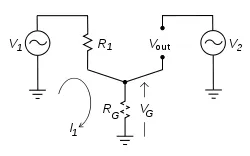
Example: Imagine a large three-phase motor straining under a heavy load is connected by a thick copper strap to the same building ground you’re using. Let’s say that thick metal strap has a loose bolt connecting it and the motor has a small ground leak. You’re in another room testing a heater and measuring air temperature with a thermocouple that generates a tiny millivolt signal. Your thermocouple meter is plugged into the wall using the same ground that the motor is connected to. You will measure temperature but it may not be accurate.
Here’s why:
Ground Loop Illustration
The simplified circuit above shows how a ground loop works. Two circuits share a common connection to ‘ground’. Ideally, the ground conductor should have no resistance (RG = 0), so the voltage drop across it, (VG), should be zero. However, if the ground conductor has a significant resistance, like our loose strap connection, then RG will not be zero and together with R1, they will make a voltage divider. When our motor ground leak current (I1) is flowing through RG from circuit 1, a voltage drop VG = I1 * RG will occur and the ground connection of both circuits will no longer be at the actual ground potential. This voltage across the ground conductor will be applied to Vout, in our example the electrical outlet powering our meter, as some varying voltage greater than ground reference zero. So, circuit 1, our motor, can introduce interference through the ground into the power source of circuit 2 (Vout), the electrical outlet we have our sensitive meter plugged into.
One way to fix this: A common solution to ground loops is to use separate grounding systems for the typical components in an electrical system. The facility power grid ground is used for safety grounding of high current devices and an isolated, very low resistance ground system, is created specifically for use with sensitive signal equipment
Staying Grounded Remember that all incoming power must return to ‘ground’ somehow, whether by a planned or an unplanned path. Either way, there are consequences to the design of electrical grounding systems. Hopefully, these two illustrations underscore the need to treat the quality of grounding at least as seriously as we do the quality of incoming power.
General As the name suggests, a surface heater is a device that raises the temperature of a surface. Now in the world of heaters, surface heaters aren’t really very sexy – they often consist of little more than a few pieces of mica and some wire. But throw in a thermocouple or a diode and some creative geometry, and they can get down-right interesting. TUTCO-Farnam Custom Products creates a vast array of surface heaters serving a multitude of industrial needs. Surface heaters are generally constructed of flat pieces of mica cut (with a CNC machine) to a specified size and shape and wrapped with resistance ribbon. The ribbon is selected to produce the wattage and voltage required for the particular application. The wound core is then ‘sandwiched’ between two (2) mica covers to complete the heater. Additional pieces of mica are sometimes utilized to mount a thermocouple or to provide additional strength or insulation. An assembled surface heater is usually less than 0.060” thick.
Sizes and shapes Surface heaters vary greatly in size – from smaller than 4” X 4” up to as large as a full sheet of mica (38” X 46”). TUTCO-Farnam produces surface heaters in numerous shapes; most are square or rectangular, but they may be round, or even irregular in shape. The real beauty of these heaters is that the mica can be cut to any shape required to conform to the surface that the application specifies. Surface heaters have even been created to line the inside of a cylindrical form by using flexible mica – a surface heater in 3-D, so to speak!
The lead wires used to connect surface heaters normally exit the heater on the sides, but their placement varies to accommodate the heater application. Lead wire may exit flat (in the plane of the heater) or perpendicular to it, or at pretty much any orientation that best suits the application.
Common Uses TUTCO-Farnam surface heaters are utilized predominantly in the foodservice industry and in laboratory uses, but any application that requires a heat source in a limited space may benefit from a surface heater. In the foodservice industry these heaters provide concentrated, focused heat for warming plates or heating enclosures. In laboratories, made-to-order heat for hot plates is available in a large variety of sizes and shapes. Applied to the sidewalls and/or bottom of a container or enclosure, surface heaters will effectively heat the product or material inside. Another industry application that uses surface heaters almost exclusively is heat transfer presses.
Electrical Ratings A wide range of heater ratings is possible with surface heaters. Most TUTCO-Farnam surface heaters are built at 120 or 240 VAC, but heaters as low as 24 volts or as high as 600 volts have been constructed. It’s even possible to design for DC voltages in a surface heater. Dual voltage surface heaters are available as well, built with a series/parallel circuit with three leads. Wattages in surface heaters are as varied as the applications – limited largely by the surface area. 100W – 1500W are available in heaters up to 10” x 10”, and larger surface heaters may produce 4500W, or more.
Heat Distribution In most surface heaters, the heat is evenly distributed across the mica surface. However, in some applications, the heat concentration is required to be ‘zoned’ into regions of warmer and cooler areas. For example, a warming shelf with sides exposed to cooling air might need to have more heat concentrated along the sides and less in the middle (where it might overcook or dry out the food held there). TUTCO-Farnam Custom Products specializes in designing heaters to meet the specific parameters required for any application.
Mounting Considerations TUTCO-Farnam surface heaters can be mounted in any position without adversely affecting the performance of the heater. When attached they are pressed firmly against the surface they are to heat. Spaces (air gaps) between the heater and the surface make the heater less effective and can cause hot spots which may result in failure. The reverse side of the surface heater should be well insulated for optimum efficiency. It goes without saying that mica supported electrical devices and water are not compatible, so adequate steps are required to keep moisture away from the heater.
Summary TUTCO-Farnam Custom Products is proud to provide custom surface heaters for a wide variety of applications. If you have an unusual area, a limited space, or just any surface that you need to be heated, give us a call or tell us about your project in our online inquiry form. We’ll be glad to work with you to create a heater of the exact size, shape, and rating to fit your specific application.