An existing customer needed a new solution for heat in a custom HVAC system used in an agriculture transport trailer that required the temperature to be controlled in a certain range. The heaters would operate in a custom under floor custom air duct and would need to able to withstand an FDA approved wash down in between loads. Traditional HVAC style heaters had been used in the past, but they had to be isolated from the area that needed the heat due to the washdowns which were causing some issues. The heaters also needed to be robust in order to withstand the vibration of the trailer as it traveled down the road.
TUTCO built a custom-designed Finned Ultima Strip Heater for this application with special terminations and mounting features. Our Ultima Strip Band heater is one of the most rugged products on the market. Its tubular heating element provide uniform heat at medium to high temperatures while resisting contamination, corrosion and vibration. It added heat where it needed to be, was able to work in the wash down environment, and was robust enough to withstand the vibration created by the trailer traveling down the road. The customer is now working on retrofit kits for existing trailers and offering it as an option on all new trailers.
by Ian Renwick – Thermal Expansion is the propensity of solid matter to increase its volume when heated. This change in volume occurs in all directions of an object in length, width, and height. The amount of change is proportional to the change in temperature, the initial dimensions of the object and by material itself. Thermal expansion can work with you or against you, depending on the how objects are arranged.
First, here are a few interesting examples of thermal expansion. The truss of the Eiffel Tower is made of iron and stands 1063 ft tall. The temperature in Paris varies through the year from about 30 to 80°F or a 50°F temperature swing. On hot days, the tower is 6″ taller than on cold days.
Railroad tracks are made of hot rolled medium carbon steel. Depending on where they’re located in the world, track might see a large temperature swing over a year, possibly as much as 80°F. Between those temperatures a mile of track varies in length by as much as 30″ or almost 2 1/2 feet between winter and summer. That expansion and contraction must be account for in track layout to avoid warping and bucking of the tracks which can lead to train derailment.
Let’s get into it: The amount of growth or an object is calculated by only having to know 3 things and multiplying them together. They are the starting dimension from where you want to measure your expansion (or contraction), the change in temperature (in °F in our examples), and the coefficient of thermal expansion (CTE) for the material (in imperial units). You can find CTEs online with a simple search, but here are a few common ones.
The prefix µ is the Greek letter mu, meaning micro or millionth. Glass and polyethylene are included in the list to show how varied different thermal expansion rates can be.
Material
CTE
Iron
5.8 - 6.5 µin/in·°F
Plain Steel
6.0 - 6.9 µin/in·°F
Stainless Steel
8.0 - 9.6 µin/in·°F
Incoloy 800
8.0 µin/in·°F
Brass
10.0 - 10.6 µin/in·°F
Aluminum
11.7 - 13.3 µin/in·°F
Pyrex Glass
2.2 µin/in·°F
Polyethylene
60 - 110 µin/in·°F (milk jug material)
Here’s how to perform some calculations. Imagine you have a cylindrical cartridge heater measuring 24″ long, and you want to know how much it will elongate if it goes from 72°F to 1000°F. The cartridge heater sheath is made of Incoloy 800. The CTE of Incoloy 800 is 8.0 µin/in·°F. That elongation factor is read as 8 millionths of an inch per inch in length per degree Fahrenheit.
Knowing those three values and multiplying them together gives you: 24in x (1000°F-72°F) x 8.0 µin/in·°F.
Written without the units to make it easier to read you have: 24 x (1000-72) x 0.000008 = 0.178″. The heater will elongate by almost 3/16″. That difference is easily measured with a tape measure.
The same calculation can be performed for the diameter of the heater. If you’re told the heater has a diameter of 0.620″ at room temperature, then its size at temperature is calculated as follows: 0.620 x (1000-72) x 0.000008 = 0.0046″. The heater will increase in diameter by almost 0.005″.
When the heater gets hot it should enlarge to snuggly fit in the hole it’s inserted into.
There is a slight downside to this. Just as the diameter of the heater gets bigger, the hole that its inserted into gets bigger too. Fortunately, the walls of the hole do not get as hot as the heater itself, so the hole expansion will be less than the heater. Additionally, if the block that the hole is in is made of plain steel, the expansion will be less still because the thermal expansion rate of plain steel is less than that of Incoloy 800.
Let’s assume the wall of the hole in the plain steel block only reaches a temperature of 800°F, that means the hole expansion, going from 0.625″, would be 0.625 x (800-72) x 0.000006 = 0.0027”.
That means the hole would enlarge from 0.625″ to 0.628″ and the heater would enlarge from 0.620″ to 0.625″. There would be a smaller gap between the heater and hole than when you started, meaning a better fit and better heat transfer.
With band heaters, it’s a similar affair, except the hotter object is the heater on the outside and the cooler object is what’s being heated, on the inside. Unfortunately, that means that band heaters get loose when they’re heated. No matter how much they’re originally tightened at room temperature they’ll always get loose.
Here’s why. A 6” diameter band heater (let’s say), made of stainless steel and heated up to 800°F enlarges in diameter by this much: 6 x (800-72) x .000008 = 0.035″.
The barrel that the heater is mounted to is made of plain steel (in this example) and experiences a temperature of 600°F. That means it expands in diameter like this: 6 x (600-72) x .000006 = 0.019″. It’s easy to see with these simple calculations that the heater expands more in diameter than the barrel, allowing the heater to become loose.
That’s why it is so important to retighten band heaters when they’re as close to operating temperature as possible, as long as it can be done safely. Conveniently, Tutco does provide a spring bolt clamping option that helps with that issue by having a positive force constantly pulling the heater closed with a heavy-duty spring that’s incorporated into the clamping mechanism.
As you can see, thermal expansion can play an important factor when it comes to fitting your heaters to your application. Depending on the temperatures operated at, the materials used, and the size of your components affect how well the conduction between components is enhanced or can be made worse.
As 3D printing have evolved, a variety of technology and techniques have been used to improve the quality of printed objects. One such technology is the use of specific heaters and sensors within the printer that play a critical role in the success of the process.
TUTCO cartridge heaters, as small as 1/4” to 1/8” in diameter and 1” to 1 1/2” long, are used inside the 3D printer extrusion heads. These heaters are responsible for melting plastic material, which is then extruded in layers to create a 3D printed object. Different types of plastic require different temperatures, and these heaters can hold temperatures anywhere from 180°C for PLA plastic to 260°C for Pure PETG plastic.
In addition to cartridge heaters, a warm print bed is also necessary for some types of plastic material. Flat silicone rubber and Kapton heaters are used to create a warm print bed. A warm print bed helps prevent warping of the finished part and improves adhesion of the first printed layer to the bed itself, which reduces the severity of contraction of earlier printed layers and prevents part curling.
Thermocouple sensors are also being used in 3D printing to measure temperature. These sensors are available in a variety of configurations, including grounded or ungrounded junctions and different conductor materials such as type K and J. They also come with adaptors attached like threaded bushings or hex head bushings in stainless or brass. Leadwire lengths can vary as required and they are available with stainless steel braid or armor covering if necessary.
As 3D printing technology continues to advance, the use of specific heaters and sensors will become increasingly important to achieve the highest quality prints possible. TUTCO engineers will continue to develop leading edge solutions for this evolving application.
Public transportation vehicles often have small heaters under the seats for passenger comfort. One mass transit company, that was renovating their older passenger cars, came to TUTCO needing a small lightweight heater for this application. Many of the existing heaters, which had been in place for years, had failed and the company that originally built the cars was no longer in business. The heaters needed to fit within a very specific envelope and installation pattern while being as lightweight as possible. The application required very little heat which meant the watt density of the heater would be very low.
TUTCO HT Mica Band Heaters offer the most comprehensive range of customization available, including distributed wattage, holes, or cut outs based entirely on the application requirement. We developed an HT Mica Band Heater with special mounting holes and terminal locations and orientations designed specifically for the application. They fit the existing space as required and provided the perfect amount of heat to take the chill off of passengers commuting to work on chilly mornings.
A high-volume garment manufacturer using a large heated fabric press to mold and form accessories faced a challenge with the Mica Band heaters used in the press. Downtime was an issue as they had no spare parts heaters on hand and the company that manufactured the press, as well as the heaters, was not domestic and no customer support from either company was readily
available. To make the situation even worse, the design of the heater was very complex with two heating zones, a large cutout, and multiple mounting holes.
The garment company sent the failed heater to us at TUTCO where we reverse engineered it. Working with the customer, we created a more robust design that delivered greater reliability with a custom-designed HT Mica Band Heater. We also worked to expedite the process to minimize downtime for the customer. TUTCO’s HT Mica Band solution delivers an efficient production line with little to no downtime, spare parts on hand and a ready source for additional parts.
Understanding the causes of heater failure will extend the life of your heater and ensure that it is working as efficiently as possible. There are three main culprits to be on guard for: physical abuse, application issues, and excessive temperature, any one of which can cause your heater to quickly fail.
Physical abuse can easily occur during the shipping and handling of a heater. Mishandling the heater can lead to damaged screw terminals or lead wires, so it is essential to take care in unpacking and installing your heater. A damaged lead wire can result in the heater element shorting out, arcing, or the heater failing very rapidly once power is supplied to it.
Application issues can develop when the heater is not used with the ideal specifications or the lead wire is damaged due to movement, such as cycling back and forth. You can avoid damage, such as lead wires being pulled from their connections, by making sure all of the components fit properly. Another common application issue is contamination from water, oil, or molten material like plastics. Corrosive material landing on the heater, especially where the lead wires connect to it, can quickly lead to heater failure.
All heaters have an upper temperature limit. Excessive temperature will shorten the heater’s life. Cartridge and band heaters are designed for conductive heat transfer. When conduction is limited, heat will be transferred using convection or radiation, which is not as efficient as conduction. If heat cannot move away from the heater quickly enough, the heater will continue to get hotter, leading to the oxidation of heater components. When oxidation builds up on wires and tubing or on the inside of the sheath in a band heater, one of two things happens: the conductor inside the oxidation fails as an open circuit or the oxide layers meet causing an arc or short resulting in heater failure. To extend the life of a heater, it is vital to create an environment where as much heat as possible is transferred through conduction. If a cartridge heater fits loosely in a hole, there will be a lack of conduction and the heater might as well be operating in open air. A band heater that is not installed snugly around a barrel or retightened after heating up will achieve less heat transfer through conduction, resulting in poor performance and ultimately a shorter life.
In order to achieve optimal results from a cartridge or band heater, follow the handling instructions, install the heater with care into the proper application environment, and ensure the heater is achieving the maximum heat transfer through conduction.
Thermodynamics, specifically heat transfer, is used throughout our daily lives, but not always thought of. A common practice of cooking breakfast would be one simple example. You place one type of media, your frying pan, onto a hot surface and apply the “heat”, which is your source of energy, to cook the food. The heat transfer that is occurring between the higher temperature stove-top and the cooler frying pan is a great practical application. It is also a simple example of the second law of thermodynamics, “Heat cannot, of itself, pass from a lower temperature to a higher temperature.” Thus, for heat transfer to occur, we can state that a temperature difference must exist between two mediums.
As we further study heat transfer and any thermal system, we will need to consider the three types of heat transfer, which are conduction, convection, and radiation. In many cases, you can have two or even all three sources of heat transfer happening simultaneously. As each form of heat transfer is briefly discussed I will list an example in the following paragraphs.
In order to fully understand how conduction, convection, and radiation are affected, you must consider the rate at which a certain medium will affect your system design. The rate at which energy or heat is absorbed or dissipated is dictated by the thermal conductivity of a material or combination of materials, temperature difference, area of the surfaces, and mass of the combined components. By varying the previously mentioned attributes, one can increase or decrease the speed and efficiency of a thermal system.
Now let’s look at a short study of each type of heat transfer. The first form is conduction. Conduction is a thermal process that occurs between two surfaces in contact with each other, where a temperature gradient exists, or even in one material that has a temperature gradient between two planes. If we use a simple experiment of a uniform bar of cross-section A, perfectly insulated on all sides except at the ends; where heat can only flow in the ‘x’ direction (see Fig. 1). If the bar is maintained at t1 on one end and t2 at the other end, Q (BTU/Hr (BTU = British Thermal Units, HR = Hours) will be transferred steadily from the entry, at location 1 to the exit at location 2. The rate of heat flow (heat flux) is directly proportional to the cross-sectional area and temperature difference from point to point of the bar. You may want to compare the cross-sectional relationship of the bar to how water flows through a pipe. The larger diameter of the pipe, the more flow of water (energy) it can transfer. If we now determine how the length of the bar will affect the heat transfer rate, we double the length (2L). It is found that the heat transfer rate is cut in half, which demonstrates that the heat transfer is inversely proportional to the length of the bar.
Fig. 1
Equation 1 shows mathematically the relationship of all the factors, where the proportionality constant, k, is a property of the material called thermal conductivity. The negative sign has been included in equation 1 to indicate a positive heat flow. The conductivity, k, is usually a function of temperature, but for moderate temperatures and temperature differences, it can be considered a constant.
Equation 1: Reference bibliography
Example: A plane wall constructed of solid iron with thermal conductivity 70 W/m°C, thickness 50 mm and with surface area 1 m by 1 m, temperature 150°C on one side and 80°C on the other.
The second form of heat transfer is convection. Convection is the transfer of heat through the motion of a liquid or gas relative to the body of material. There are two types of convection, forced convection, and natural convection. If the motion of the fluid is caused by the different densities initiated by the different temperatures in various locations of a fluid, it is known as natural convection. If the motion of the fluid is caused by an external force, such as a fan or blower in air heating then it is considered forced convection. With natural convection, the minor temperature differences in a fluid can cause heat transfer. For example, a room in your house could have small temperature differences from an outside wall to an interior wall. Those hot and cold particles coming into contact with the wall will collide and cause a transfer of energy. The equation for Newton’s law of cooling helps explain how basic convection is mathematically represented (see Equation 2). It is much more in-depth to explain forced convection, so that could be covered in future articles.
Equation 2: Reference Bibliography
Q = heat-transfer rate (BTU/hr)
A = heat-transfer area (FT2)
∆T = temperature difference between the surface and the bulk of the fluid away from the surface (°F)
h = coefficient of heat transfer (BTU/hr – ft² – °F)
Example: Fluid flows over a plane surface 1 m by 1 m with a bulk temperature of 50°C. The temperature of the surface is 20°C. The convective heat transfer coefficient is 2,000 W/m2°C.
The third and final form of heat transfer is radiation. Radiant heat transfer differs from the other forms. Radiation does not require any medium to transfer heat. Radiant heat transfer is similar to the “electromagnetic phenomenon” similar to light, x-rays, and radio waves. In this case, a transfer of heat occurs when the absorption of energy is greater than what is radiating from the same body. A body that absorbs all radiation and does not radiate any heat energy itself is considered a “blackbody.” The small amount of heat that is reflected is considered the body’s reflectivity, the amount of heat absorbed is known as absorptivity, and the effectiveness of as a thermal radiator is known as emissivity. The radiant heat transfer rate is shown in equation 4.
Equation 4
σ = Stefan-Boltzmann constant = 0.173 x 10 – 8 BTU/hr – ft2 – °R4 (in SI – 5.669 x 10⁻⁸ Watts/m2 – °K4)
Fe = emissivity factor
FA = Geometric factor to allow for the average solid angle through which one surface “sees” the other
Example: Radiation from the surface of the Sun If the surface temperature of the sun is 5800 K and if we assume that the sun can be regarded as a black body the radiation energy per unit time can be expressed by modifying (1) like
q / A = σ T4
= 5.6703 10-8 (W/m2K4) (5800 (K))4
= 6.42 107 (W/m2)
All three of the previously mentioned heat transfer factors must be considered when sizing a heater for any application. If a band, cartridge, or a strip heater, is selected, all of these elements work on the same design principles. The system can be insulated to improve efficiency during operation and controlled to more accurately provide heat. The final power requirements and efficiencies will depend on a well-designed system that eliminates heat loss and offers close control. A good rule of thumb, after the initial requirements are determined, that a designer uses a 25% service factor or a 1.25 multiplier for the wattage output of the system.
Bibliography Equation 1, 2, 3 and Table 1 from “Thermodynamics and Heat Power”, Sixth Edition by Irving Granet and Maurice Bluestein, Copywrite 2000, Published by Prentice-Hall, Inc., Upper Saddle River, New Jersey 07458
Footnotes 1 See page 581, from “Thermodynamics and Heat Power”, Sixth Edition by Irving Granet and Maurice Bluestein, Copy-write 2000, Published by Prentice-Hall, Inc., Upper Saddle River, New Jersey 07458
Electric heaters come in all shapes and sizes. One of the most popular is the cartridge heater, which can be described generically as a round tube with leads exiting typically at one end that, when attached to an electrical source, produces heat.
Selecting a cartridge heater is no different than selecting other types of heating elements. There are many factors you must consider such as the application, environmental conditions, temperature capabilities and voltage. If this information is not readily available or not known, consider contacting a local distributor in your area that specializes in heating applications for their input. The most common types of cartridge heaters are standard loose pack and standard swaged construction.
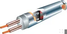
Figure 1. In a standard loose pack cartridge heater, ceramic cores provide the electrical insulation for the coiled resistance wire that passes through them.
Standard Loose Pack
The first cartridge heater design was the standard loose pack. Its construction begins with a stainless-steel tube, and extruded ceramic cores with holes running their length are inserted. These ceramic cores provide the electrical insulation for the coiled resistance wire that passes through them, positioning the resistor wire near the center of the heater. Once the core and wire are inserted, magnesium oxide powder is sifted into the holes to assist in dissipating heat. One end of the heater is closed with a metal-end disk and, depending on design, may or may not be watertight. The other end of the heater where the power leads exit the heater typically is sealed with a ceramic cap. Various lead wire styles and lead wire protection are available (figure 1).
Due to the nature of its construction, the loose pack cartridge heater is limited in its ability to produce heat, or watts per square inch. Depending on the application, 40 W/in2 usually is the maximum for this heater design.
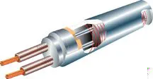
Figure 2. In a high temperature cartridge heater, the core assembly consists of a round, crushable magnesium oxide core with two holes running through its length where resistance wire is precision-wound around the core.
High Temperature, Swaged Construction
As the name describes, high temperature swaged cartridge heaters offer superior heating performance vs. standard loose pack cartridge heaters. Because they are constructed differently, they allow for increased watt densities — up to 100 or 150 W/in2 under certain conditions.
The construction of high temperature cartridge heaters positions the resistor wire close to the metal sheath. Locating the resistance wire next to the sheath provides better internal heat transfer from the wire to the sheath. Most high temperature swaged cartridge heaters utilize an Incoloy or stainless-steel tube into which the core assembly is inserted. Heater operating temperature and application environment dictate the choice of sheath material.
The core assembly consists of a round, crushable magnesium oxide core with two holes running through its length, where resistance wire is precision-wound around the core. Two nickel pins pass through the holes in the core and make contact with each end of the resistance wire. This assembly is centrally positioned in the tube and surrounded by magnesium oxide powder. The entire assembly is compacted by a swaging operation to create a dense heater that provides good heat transfer from the resistance wire to the sheath while maintaining dielectric strength. One end of the heater is closed with a metal end-disk that is welded in place to provide a watertight seal. The other end of the heater where the power leads exit the heater typically is sealed with a ceramic cement. Various leadwire styles and leadwire protection are available (figure 2).
Don’t Fit for Failure
Why do some cartridge heaters fail prematurely? The most common reason is due to a poor fit between the heater and the hole it is in. In general terms, a loose fit results in poor heat transfer. When heat transfer to the application is poor (i.e., the heat has nowhere to go), the resistance wire runs excessively hot inside the heater. This leads to excessive oxidation and eventual heater failure. Heat buildup also can cause other problems inside the heater and break down the components. The best thing for a cartridge heater is a good fit in the hole into which it is inserted.
As a general rule, heaters are manufactured 0.005″ smaller than the indicated nominal diameter to maximize heat transfer and minimize heater removal problems. Due to thermal expansion, the cartridge heater has an increased diameter and length at its operating temperature that fills this 0.005″ gap, resulting in good heat transfer.
Common Customization Options
A cartridge heater can be customized to accommodate adverse application conditions that may inhibit acceptable performance and expected operational life. Some of the more common accessories include:
Internal Thermocouples.
Thermocouples can be used to evaluate the heat transfer efficiency of an application. By measuring and improving heat transfer, you can cut energy costs and improve heater life. Cartridge heaters can be built with internal thermocouples that either can be ungrounded or grounded to the sheath. The two most common thermocouple types are J and K, though the latter is much less common.
Flanges.
Because of existing or anticipated conditions, a flange can be attached near the lead end of a heater by brazing or welding. In applications where heaters are subjected to vibration or impact, or where the heater is mounted in a vertical position, the flange can be held in place with screws to maintain heater position.
Threaded Bushings.
Various styles of threaded bushings in brass or stainless steel can be attached to the cartridge heater by brazing or welding, depending on the material requested. The most common application is where the heater is to be screwed into a container to heat fluids such as water or oils. With immersion applications, heater position is an important consideration: It should be positioned so that the fluid level will never expose the heater while it is in operation. Another common application of threaded bushings is to assist in heater removal. A simple twist with a wrench on the hex head of a bushing can assist in breaking a heater free when frozen in a hole.
Epoxy Seals.
Epoxy seals help protect a heater against moisture and contamination from oil, cleaning solvents, plastic material, fumes and organic tapes. These seals are effective to 500oF (260oC) during continuous operation. Other sealing materials also are available.
Leadwire Termination Options.
The termination area of a cartridge heater frequently requires special attention because it is one of the most abused sections of the heater. Excessive temperatures, leadwire flexing, abrasion and contamination are conditions that can be addressed by specifying certain accessories.
Mica Tape Leads.
In general, fiberglass-insulated leadwire with a temperature rating of 482oF (250oC) is used on cartridge heaters. In applications where leads may be exposed to much higher temperatures — resting in a channel of a hot platen, for example — a mica-tape-insulated leadwire can provide a temperature rating of 842oF (45oC).
Stainless-Steel Braid or Armor.
Specifying stainless-steel braid over the leads will help them resist abrasion. Similarly, stainless-steel armor will protect against abrasion and some types of contamination such as solid particles and melted plastic. Applying braid or armor will not create a waterproof condition around the leads.
Strain Relief. When flexing of the leads is present, a strain relief may be attached to the heater and leads to minimize excessive lead flexing where they exit the heater.
Lead Area Sealing.
Sealing can be accomplished by various methods; each has its own temperature limit. When used in conjunction with specific insulated leads, sealing may block certain contaminants from entering the heater. In general, a cold zone between the seal and the active (hot) area of the heater is required. The most popular sealing materials are epoxy, Silicone RTV and Teflon.
Distributed Wattage.
When specified, distributed wattage can help even out the temperature profile across the length of the heater. This feature is helpful in applications such as a sealing bar, where uniform temperature across the heater is required.
No-Heat Sections.
Unheated sections are recommended in applications where leads could be exposed to excessive heat, thus requiring a cooler lead end. Unheated sections also can be specified when heat is not required along the entire length of the cartridge heater.
Three-Phase Construction.
Heaters can be built for use with three-phase power. Be sure to specify if the power source is three-phase delta or three-phase Y (also known as three-phase star).
Dual Voltage.
Heaters can be built to operate at two different voltages.
Zoned Heaters.
Heaters can be built with sections that are independently powered and controlled.
Square Cartridge Heaters.
Both standard loose pack and high-temperature cartridge heaters can be built with a square cross section. The most common square sizes available are 3/8″, 1/2″ and 5/8″.
As with other types of electric heating elements, many other options are available, including:
Teflon-, PVC- or Neoprene-insulated leadwires.
Lead end connectors (slip-ons, rings, spades, forks, etc.).
Screw terminals exiting the heater at the same end or at opposite ends.
Ground wires.
Fiberglass or heat shrink sleeving over leads.
Special plugs.
Inline thermostats, thermal fuses or thermistors.
Brass or exotic steel sheaths.
Electropolished or passivated sheaths.
Bent heater configurations.
So, the next time you are selecting a cartridge heater, consider how customizing a cartridge heater to suit your application can improve productivity and extend heater life.
Follow this step-by-step process to learn how to size a heating system for your process application.
Calculating the wattage requirements to heat a system is a straightforward process as long as all the possibilities of heat energy flowing in and out of the system are considered. Heat requirements that must be considered are:
Initial heat for startup of the system, usually from ambient temperature to the desired processing temperature.
Losses due to materials changing phase, either during initial heat-up or while processing (melting a solid to a liquid or boiling a liquid to a gas).
Heating of material being processed during operation.
Heating of material flowing through the process such as a liquid that will be heated and pumped to be used elsewhere.
Heat losses to the environment due to conduction, convection, and radiation.
Before beginning the calculations, it is important to realize the distinction between energy and power and their relationship to wattage requirements. In metric units, power is measured in watts (W) and energy is measured in watts multiplied by hours (W x hr). In English units, energy is measured in British thermal units (BTUs) and power is measured in BTU/hr.
It also should be noted that the difference between the starting temperature and the final temperature during the application of power commonly is referred to as delta T (ΔT). If a process is started at room temperature, say 80oF, and the application process temperature is 800oF, then ?T is 800oF minus 80oF, or 720oF.
Initial Heat for Startup
The first calculation involves determining the heat required to raise the system temperature to the desired temperature. All system components must be considered. In the simplest case, a block of material is heated; in more complex situations, calculations for multiple materials must be performed.
The energy (E) required to raise the temperature of a material by ΔT is calculated using the following formula:
EInitial = Weight of Material x Specific Heat of Material x ΔT
An example will help demonstrate, so I will use examples throughout. In this case, suppose you wanted to calculate the energy required to raise a 23 lb block of tin from an ambient temperature of 70oF to 300oF, given that the specific heat of tin is 0.056 BTU/lb oF. Knowing that 1 BTU equals 0.2930711 W-hr, the specific heat of tin also can be written as 0.0164 W-hr/lb oF. Therefore:
ΔT = 300oF – 70oF = 230oF
EInitial = 23 lb x 0.0164 W-hr/lb oF x 230oF
EInitial = 86.8 W-hr
This means that it will require 86.8 W of power to raise the temperature of a 23 lb block of tin from 70 to 300oF in one hour. Because wattage requirements are calculated based on one-hour increments, the requirements for faster or slower heat-up times are calculated proportionally. If the temperature needs to be reached faster, say in a half-hour, then the wattage requirement would be doubled.
Losses Due to Material Phase Changes
If the system being heated contains material that will pass through a phase change (melt or boil), the calculations are slightly more complex and have to be broken into parts, but they follow the same rules. Imagine a system that is heated from 70 to 300oF. Contained in the vessel being heated is a mass of Alloy ABC, which melts at 200oF. The wattage requirement of heating the container is calculated as shown above, but the heating of Alloy ABC must be done in two parts.
In this case, the wattage requirement is calculated from ambient (70oF) to the melting point (200oF) for Alloy ABC using the specific heat for Alloy ABC as a solid. A second calculation is performed from 200 to 300oF using the specific heat for Alloy ABC in a liquid state. Moreover, there is additional energy required to “push” the material from one state to another and is calculated as follows:
EPhaseChange = Latent Heat of Fusion x Weight
Or, in the case of boiling a liquid, the equation reads:
EPhaseChange = Latent Heat of Vaporization x Weight
Continuing the example, assume the latent heat of fusion of Alloy ABC is 100 BTU/lb and it weighs 6 lb. You need to calculate the energy required to melt it. To solve it, you know 1 BTU is 0.2930711 W-hr. So, the latent heat of fusion of Alloy ABC also can be written as 29.30711W-hr/lb.
Remember that this value does not include the energy required for Alloy ABC to reach its melting point or the desired temperature after melting. That must be calculated separately as stated above.
Material Heating During Processing
Once the process temperature is reached, the process can begin running. Energy losses caused by materials entering the system during processing now must be considered, if applicable.
If the process involves heating pieces of plastic to the desired temperature at a rate of 10 pieces/hr, then the wattage required to heat that material must be calculated. The method is the same as for initial heat-up. Remember that if each piece of plastic weighs 1.764 oz (50 g), then 17.64 oz (500 g) of material are processed in one hour, which is the time basis for all the calculations. Call this number EProcess.
Similarly, if a fluid is flowing through the process and requires heating to the desired temperature, its wattage requirements must be calculated. The equation is very similar to earlier equations:
EProcess = Weight of Material Flowing per Hour x Specific Heat of Material x ΔT
Suppose a circulating pump passes 150 lb of seawater through a system every 10 min. The water enters at 110oF and must be at 160oF when it exists. Assuming the specific heat of seawater is 0.95 BTU/lb oF, how much wattage is required?
To solve it, you know that 1 BTU is 0.2930711 W-hr, so the specific heat of seawater also can be written as 0.278 watt•hr/lboF. Therefore:
EProcess = 150 lb x 0.278 W-hr/lb oF x (160oF – 110oF)
EProcess = 2088.1 W-hr
If it takes one hour to pass through the system, approximately 2,090 W are required to raise the temperature of the seawater. Because the seawater needs to be heated in 10 min, then the wattage requirement is approximately 2,090 W multiplied by (60 min/10 min), or 6, which is approximately 12,540 W.
Heat Losses to the Environment
Besides determining the heat required to raise the material to the desired temperature, the losses to the environment also must be considered.
In the earlier tin block example, as the block warms to 300oF, it also loses heat to the environment. This means that the earlier calculation of 86.8 W-hr is not enough energy for the block of tin to reach 300oF in 1 hr. Some of the energy bleeds into the environment and is not used to raise or maintain the temperature of the block. Losses to the environment occur during heat-up and after the process temperature is reached.
There are three types of heat transfer that can result in heat losses from a system to the environment:
Conduction Losses.
These occur when a hot object is in touching contact with a cooler object and heat energy passes from the hot object to the cool one.
Convection Losses.
These occur when heat energy is carried away from a system by surrounding fluids of gases or liquids. The calculations involved with convection can be complex, but they can be estimated to a satisfactory degree of accuracy.
Radiation Losses.
These occur in the absence of any touching contact or transfer medium and is a form of electromagnetic radiation. Radiation is the manner in which heat travels from the sun to the earth through the vacuum of space.
Considering conduction losses first, the heat losses (L) are calculated using the following formula:
LConduction = Thermal Conductivity of Material Accepting Heat x Area of Contact x ΔT x 1 Hour Per Thickness of Material Accepting Heat
To extend the tin example above, assume the block of tin is in the shape of a cube measuring 4.44″ on each side and resting on a plate of 0.5″ thick mica. Calculate the conduction loss, given that the thermal conductivity of mica is 3.1 BTU x in/(hr x ft2 x oF).
To solve for this, you know that 1 BTU is 0.2930711 W-hr, the thermal conductivity of mica also can be written as 0.91 W-hr x in/(hr x ft2 x oF).
Conduction losses only occur where the tin is in contact with the mica, so the losses only occur through the bottom face of the block and are calculated as follows:
LConduction = 0.91 W-hr•in/(hr•ft2•oF) x (4.44 in2) x 230oF x 1 hr / 0.5″ x (1 ft2 / 144 in2)
LConduction = 57.3 W-hr
Heat losses due to convection are more difficult to calculate because there are many ways for heat to be removed from an object through a surrounding medium. The main challenge, among others, is due to the fact that the convection medium can be motionless or flowing, referred to as natural convection or forced convection. Convection rates also are affected by the orientation of the object in the medium due to the effects of convection boundary layers in the medium. For example, a hot steel plate that is oriented horizontally in still air loses heat to its surroundings at a different rate than if it is oriented vertically.
Convection loss calculations can be extremely complex, involving fluid mechanics calculations and numbers with names like Reynolds, Prandlt, Nusselt, Rayleigh, Graetz and Grashof. Luckily, there are ways to greatly simplify these calculations, and many tables and charts have been developed to help with most convection situations. Any good book on heat transfer will assist with these calculations.
A simplified formula for calculating the heat loss due to natural convection is:
LConvection = Surface Loss (W/in2) x Area x 1 hr
Continuing the tin block example, assume the block resting on the mica plate is surrounded by air that is not moving, except for that which is rising after being warmed by the block. Calculate the convection loss, given that the surface loss at 300oF is 0.7 W/in2.
To find the solution, you know that the exposed surface area of the five sides of the tin cube is 5 multiplied by 4.44 in2. Therefore:
LConvection = 0.7 W/in2 x 98.568 in2 x 1 hr
LConvection = 69.0 W-hr
The calculation becomes more complex when a fluid (like air) is moving over a heated object at a known flow rate (usually expressed in cubic feet per minute, or cfm). Losses due to radiation usually are insignificant at low temperatures, but they can be a large contributor of heat loss at temperatures above 500oF and should be considered when calculating wattage requirements. The material and surface finish of an object determines its emissivity. A perfectly radiating “blackbody,” by definition, has an emissivity of 1. Emissivity is a number used to compare the radiation from an object to a perfectly emitting blackbody. Emissivity usually is difficult to know exactly, but many tables exist for various materials and surface finishes. So, the formula for calculating heat loss due to radiation is:
LRadiation = Radiation Loss (W/in2) x Area x Emissivity x 1 hr
For example, assume the tin block has a radiation loss of 1.1 W/in2 and an emissivity of 0.04. Suppose you wanted to calculate the radiation loss. You know the exposed surface area of the five sides of the cube that can radiate heat is 5 multiplied by 4.44 in2, or 98.568 in2.
LRadiation = 1.1 W/in2 x 98.568 in2 x 0.04 x 1 hr
LRadiation = 4.3 W-hr
Final Wattage Requirement Determination
Now that all the wattage requirements and losses are known, it is time to calculate the wattage required for the tin block application.
To recollect, a block of tin resting on a 0.5″ thick mica plate is being heated from 70 to 300oF and has heat losses via conduction, convection, and radiation. Two numbers must be calculated.
The wattage required to achieve the desired temperature (initial heat-up power).The wattage required to maintain the desired temperature.
The higher of the two is the wattage requirement. When calculating the initial heat-up power, the initial power required for the system must be high enough to heat the system and compensate for any losses while reaching that temperature.
When a system is at ambient temperature, its losses are zero. When a system is at the desired temperature, its losses are 100 percent. During the heat-up time, the losses increase and must be included in the initial power requirement. Avoiding the integration calculation, it can be approximated that the losses are about 65 percent of the 100 percent loss amount during the heat-up period. Therefore, the wattage requirement during heat-up is calculated as follows:
It can be seen that the power required to bring the block to temperature (171.7 W) is greater than the power required to maintain it at temperature (130.6 W). Therefore, 171.7 W will bring the tin block to temperature in 1 hr and be more than enough to maintain the desired temperature when controlled properly.
It is necessary to increase that amount by a safety factor to cover for any errors in the simplifications made during the calculations. Depending on the critical nature of the application, a good rule of thumb is to apply a safety factor of 10 percent to 25 percent. If a safety factor of 20 percent is used, simply multiply the requirement by 1.2. Applying a safety factor of 20 percent to 171.7 W-hr results in 206.0 W-hr.
Now that the wattage requirement is known, proceed with selecting the best method of applying heat to the system.
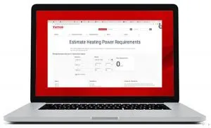
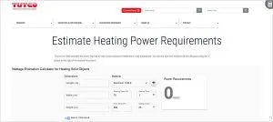
TUTCO’s online Wattage Calculator on the TUTCO website, is a valuable tool in determining process heat solutions. It will provide a good approximation of the power required. The calculator app applies a chosen safety factor to calculate the necessary wattage needed.
Let’s explore the relationship between heat and temperature.
We all know that adding heat raises the application temperature, but while heat is being added to a system, heat is also lost due to a variety of factors. There is a balancing act of heat entering and leaving the system. Eventually the application stabilizes at a temperature that represents the balance of heat entering and leaving the system.
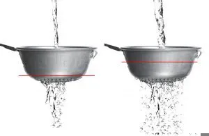
A fairly good analogy is that of water running through a colander.
If you were to hold the colander (the system) under running water (the heat source) some water will leak through the colander (the loss of heat to the environment), but after a few moments the water level inside the colander would stabilize at a constant level. That’s the heat balance in the system and corresponds to a certain temperature. If the water level were lower it means the system would be cooler.
Imagine you can change the size and spacing of the holes in the colander. This would represent the different materials you could potentially be heating, like Steel, Aluminum, Copper or any other material.
Continue to think of the temperature of the system as the level of water you’re able to maintain in the colander. The more water you run into the colander the more wattage (or power) you’re putting into the system. As the water enters the colander, it leaks out. It leaks more as you run water faster into the system because the water in the colander rises, exposing itself to more holes to leak through. Eventually you reach a condition where the water level remains constant (as water is being poured into the colander) and the water leaking from the colander remains at a constant flow as well. When the water level remains constant, the water entering the colander equals the water leaving the colander. That constant water level is equivalent to the constant temperature that the system has achieved.
With similar colanders (or similar systems to be heated) different flow rates cause different amounts of water loss (heat loss) and different stable water levels (final temperatures).
If you were to repeat the process with a different system material, you would mimic that by altering the geometry of the colander you’re using. Maybe the holes would be smaller and farther apart. That type of colander would behave differently than the first and the system could get to a constant water level faster, and also attain a different water level. This analogy demonstrates that altering the system material (the colander geometry) will cause the system to level off at a different temperature in a different amount of time.
TUTCO’s Wattage Calculator considers several material properties used in your system to determine the input power required for your system to reach a specific temperature in a certain amount of time.
There are three types of heat loss in a given system. There are losses due to convection, radiation and conduction. The first two are calculated based on the surface area of the system and the direction in which the surfaces face (upward, downward, sideways) because those directions will slightly affect the rate of convective heat loss. For both convection and radiation heat losses, the amount of loss is largely determined by the surface temperature. A hotter surface will lose more heat than a cooler one.
The third type of heat loss is conduction in which heat is lost through objects that are touching the system to be heated. Conduction losses cannot be accurately calculated with a simple tool like our wattage calculator because the geometries of things that could be touching the system to be heated are numerous. Is the system sitting on a large aluminum plate? Is the system held in the air with thin supports? Is the system part of a much bigger machine where it is completely encompassed by large pieces of steel? With this wide variety of options heat loss can’t be modelled with a simple tool. For the time being, conduction losses are ignored and can be accounted for by adding a 20% or 30% safety factor to the final wattage number.
Begin using the tool by entering the dimension of what’s being heated being sure to get the orientation of your object correct. The tool allows you to describe a rectangular solid with length, width and height (or thickness) numbers. If you need to represent a cylinder, approximate it with the closest rectangular solid you can use. The orientation of the object is important because an object in a vertical orientation will lose heat a little differently than the same object in a horizontal orientation.
Once you are satisfied with the object dimensions, select the material you’ll be heating. The drop-down list contains a large variety of materials to choose from. Once selected, the appropriate material properties will populate the specification box at the bottom left of the calculator.
Next, you’ll enter the starting temperature and final temperature you want to achieve, and the amount of time you want to reach that final temperature in. All these numbers can have a big effect on the wattage required to heat the system. Remember to enter your time number in hours, for example 30 minutes = 0.5 hrs, 15 minutes = 0.25 hrs and 5 minutes = 0.083 hrs, etc.
A final wattage number will be shown on the right side of the tool. You can adjust the numbers in the calculator and see how the wattage requirement changes.
The TUTCO Wattage Calculator Tool should not be used if the final temperature selected is above the material’s melting point. The tool does not consider the latent heat of fusion, nor does it consider the thermal properties of the material in a liquid state, which are different from the properties when solid.
A safety factor is provided for a couple of reasons. Any wattage calculator approximates the real world, and since there are always inaccuracies in any calculator, you want to add a little extra to make sure you’ve accounted for those inaccuracies. 20% is a good number to start with. This will ensure you have enough wattage for your application. Because this tool doesn’t take conduction into account, it’s best to set the safety factor to about 30%.
The TUTCO Wattage Calculator is an ideal tool for beginning the process of identifying the heating and temperature needs of your application. The results will give you a better understanding of your process and the wattage required to make it work. With this information in hand, TUTCO can provide you with the ideal heating solution.


 There are three types of heat loss in a given system. There are losses due to convection, radiation and conduction. The first two are calculated based on the surface area of the system and the direction in which the surfaces face (upward, downward, sideways) because those directions will slightly affect the rate of convective heat loss. For both convection and radiation heat losses, the amount of loss is largely determined by the surface temperature. A hotter surface will lose more heat than a cooler one.
 The TUTCO Wattage Calculator Tool should not be used if the final temperature selected is above the material’s melting point. The tool does not consider the latent heat of fusion, nor does it consider the thermal properties of the material in a liquid state, which are different from the properties when solid.