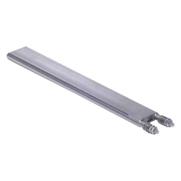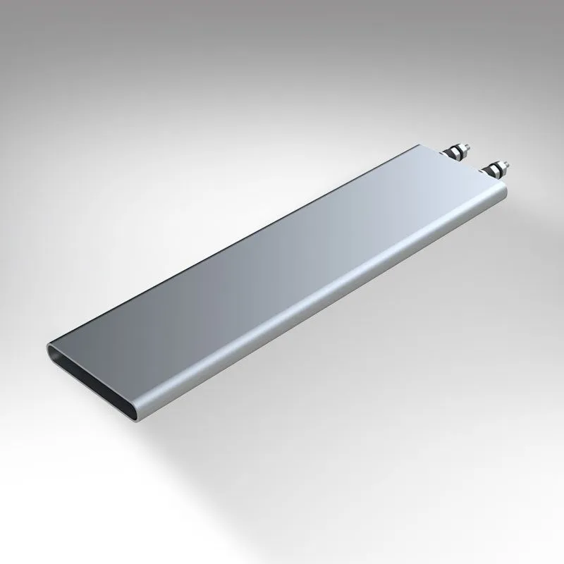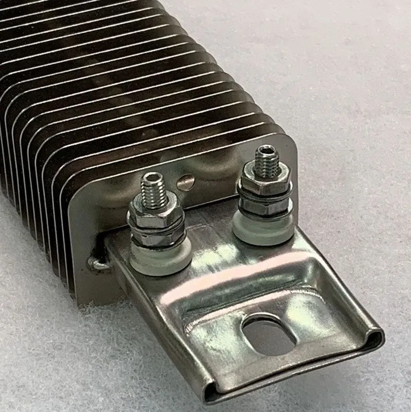
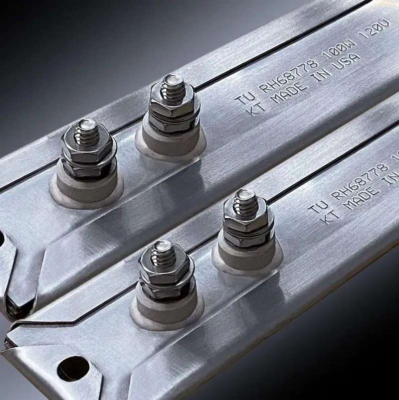
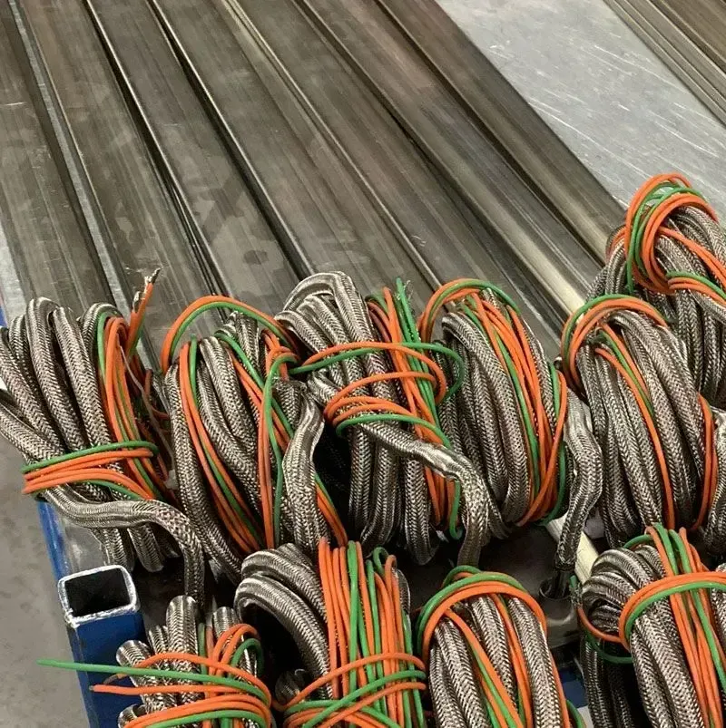
TUTCO offers four different types of strip heaters suitable for various applications.
Ultima Strip Heaters utilize a reliable tubular heating element encased in a stainless-steel sheath. Withstanding corrosive and high-temperature environments (up to 1200 °F / 648 °C), they are suitable for demanding applications. Offering higher watt densities, faster heat-up times, and longer service life than conventional strip heaters, they are customizable with various mounting options, terminations, and lengths. They can also be finned for air heating applications if required.
HT Mica Strip Heaters are cost-effective and reliable in providing uniform heat over flat surfaces. With a maximum operating temperature of 900 °F / 482 °C, they are best suited for low to moderate temperatures. Available in various shapes, sizes, and termination styles, they are versatile for different applications, including food warming, heating enclosures, and packaging machinery.
Permaheat Strip Heaters are TUTCO’s most rugged strip heater. Designed for heavy-duty applications, they use a tubular heating element for excellent heat transfer and resistance to contamination. Featuring an aluminum body, they conform better to slightly irregular surfaces due to high thermal conductivity and low thermal expansion coefficient. Customizable with various mounting options, terminations, shapes, and sizes, they have a maximum temperature of 600 °F / 315°C, and are suitable for medium to low-temperature applications.
Ceramic Strip Heaters can withstand higher temperatures than the others and are limited to 40 to 45 watts per square inch, depending on the application. Consisting of a stainless-steel sheath containing ahigh-temperature ceramic insulating nichrome wire coil, they utilize Magnesium oxide (MgO) to fill any air pockets, ensuring optimal heat transfer. With a maximum operating temperature of 1000 °F / 538°C, they are suitable for medium-temperature applications and can be customized with fins, mounting options and various terminations. Available in lengths from 6” to 160” and always 1 1/2” wide, with a thickness of 5/16” or 3/8”.
For proper mounting, follow these steps:
Choose a suitable location with adequate clearance, ventilation (if required), and ensure safe installation.
Clean and prepare the mounting surface, ensuring it is flat and smooth.
Apply a thin layer of thermal transfer compound to the back of the heater to improve heat transfer and fill any small air gaps, using non-metallic based thermal paste like milk of magnesia or boron nitride spray.
Secure the heater to the surface using clamps, bolts, screws, or rivets, avoiding overtightening or deforming the heater.
Connect the electrical wiring according to specifications and codes, using appropriately sized wire, terminals, connectors, and insulation.
While not mandatory, it’s recommended to have someone check the set up and electrical wiring for safety before applying power, prioritizing safety at all times. Double-checking the installation can prevent any potential hazards and ensure the strip heater operates efficiently and reliably.
Thermodynamics, specifically heat transfer, is used throughout our daily lives, but not always thought of. A common practice of cooking breakfast would be one simple example. You place one type of media, your frying pan, onto a hot surface and apply the “heat”, which is your source of energy, to cook the food. The heat transfer that is occurring between the higher temperature stove-top and the cooler frying pan is a great practical application. It is also a simple example of the second law of thermodynamics, “Heat cannot, of itself, pass from a lower temperature to a higher temperature.” Thus, for heat transfer to occur, we can state that a temperature difference must exist between two mediums.
As we further study heat transfer and any thermal system, we will need to consider the three types of heat transfer, which are conduction, convection, and radiation. In many cases, you can have two or even all three sources of heat transfer happening simultaneously. As each form of heat transfer is briefly discussed I will list an example in the following paragraphs.
In order to fully understand how conduction, convection, and radiation are affected, you must consider the rate at which a certain medium will affect your system design. The rate at which energy or heat is absorbed or dissipated is dictated by the thermal conductivity of a material or combination of materials, temperature difference, area of the surfaces, and mass of the combined components. By varying the previously mentioned attributes, one can increase or decrease the speed and efficiency of a thermal system.
Now let’s look at a short study of each type of heat transfer. The first form is conduction. Conduction is a thermal process that occurs between two surfaces in contact with each other, where a temperature gradient exists, or even in one material that has a temperature gradient between two planes. If we use a simple experiment of a uniform bar of cross-section A, perfectly insulated on all sides except at the ends; where heat can only flow in the ‘x’ direction (see Fig. 1). If the bar is maintained at t1 on one end and t2 at the other end, Q (BTU/Hr (BTU = British Thermal Units, HR = Hours) will be transferred steadily from the entry, at location 1 to the exit at location 2. The rate of heat flow (heat flux) is directly proportional to the cross-sectional area and temperature difference from point to point of the bar. You may want to compare the cross-sectional relationship of the bar to how water flows through a pipe. The larger diameter of the pipe, the more flow of water (energy) it can transfer. If we now determine how the length of the bar will affect the heat transfer rate, we double the length (2L). It is found that the heat transfer rate is cut in half, which demonstrates that the heat transfer is inversely proportional to the length of the bar.
Fig. 1
Equation 1 shows mathematically the relationship of all the factors, where the proportionality constant, k, is a property of the material called thermal conductivity. The negative sign has been included in equation 1 to indicate a positive heat flow. The conductivity, k, is usually a function of temperature, but for moderate temperatures and temperature differences, it can be considered a constant.
Equation 1: Reference bibliography
Example: A plane wall constructed of solid iron with thermal conductivity 70 W/m°C, thickness 50 mm and with surface area 1 m by 1 m, temperature 150°C on one side and 80°C on the other.
The second form of heat transfer is convection. Convection is the transfer of heat through the motion of a liquid or gas relative to the body of material. There are two types of convection, forced convection, and natural convection. If the motion of the fluid is caused by the different densities initiated by the different temperatures in various locations of a fluid, it is known as natural convection. If the motion of the fluid is caused by an external force, such as a fan or blower in air heating then it is considered forced convection. With natural convection, the minor temperature differences in a fluid can cause heat transfer. For example, a room in your house could have small temperature differences from an outside wall to an interior wall. Those hot and cold particles coming into contact with the wall will collide and cause a transfer of energy. The equation for Newton’s law of cooling helps explain how basic convection is mathematically represented (see Equation 2). It is much more in-depth to explain forced convection, so that could be covered in future articles.
Equation 2: Reference Bibliography
Q = heat-transfer rate (BTU/hr)
A = heat-transfer area (FT2)
∆T = temperature difference between the surface and the bulk of the fluid away from the surface (°F)
h = coefficient of heat transfer (BTU/hr – ft² – °F)
Example: Fluid flows over a plane surface 1 m by 1 m with a bulk temperature of 50°C. The temperature of the surface is 20°C. The convective heat transfer coefficient is 2,000 W/m2°C.
The third and final form of heat transfer is radiation. Radiant heat transfer differs from the other forms. Radiation does not require any medium to transfer heat. Radiant heat transfer is similar to the “electromagnetic phenomenon” similar to light, x-rays, and radio waves. In this case, a transfer of heat occurs when the absorption of energy is greater than what is radiating from the same body. A body that absorbs all radiation and does not radiate any heat energy itself is considered a “blackbody.” The small amount of heat that is reflected is considered the body’s reflectivity, the amount of heat absorbed is known as absorptivity, and the effectiveness of as a thermal radiator is known as emissivity. The radiant heat transfer rate is shown in equation 4.
Equation 4
σ = Stefan-Boltzmann constant = 0.173 x 10 – 8 BTU/hr – ft2 – °R4 (in SI – 5.669 x 10⁻⁸ Watts/m2 – °K4)
Fe = emissivity factor
FA = Geometric factor to allow for the average solid angle through which one surface “sees” the other
Example: Radiation from the surface of the Sun If the surface temperature of the sun is 5800 K and if we assume that the sun can be regarded as a black body the radiation energy per unit time can be expressed by modifying (1) like
q / A = σ T4
= 5.6703 10-8 (W/m2K4) (5800 (K))4
= 6.42 107 (W/m2)
All three of the previously mentioned heat transfer factors must be considered when sizing a heater for any application. If a band, cartridge, or a strip heater, is selected, all of these elements work on the same design principles. The system can be insulated to improve efficiency during operation and controlled to more accurately provide heat. The final power requirements and efficiencies will depend on a well-designed system that eliminates heat loss and offers close control. A good rule of thumb, after the initial requirements are determined, that a designer uses a 25% service factor or a 1.25 multiplier for the wattage output of the system.
Bibliography Equation 1, 2, 3 and Table 1 from “Thermodynamics and Heat Power”, Sixth Edition by Irving Granet and Maurice Bluestein, Copywrite 2000, Published by Prentice-Hall, Inc., Upper Saddle River, New Jersey 07458
Footnotes 1 See page 581, from “Thermodynamics and Heat Power”, Sixth Edition by Irving Granet and Maurice Bluestein, Copy-write 2000, Published by Prentice-Hall, Inc., Upper Saddle River, New Jersey 07458
Mica is a superb insulating material that is versatile and cost-effective for heater design.
At TUTCO-Farnam the majority of our custom-designed heaters use mica board machined to meet the customer’s specifications. A variety of types and thicknesses of mica are available and are selected for use based on the parameters required. Design variations using mica are virtually endless and can be customized to fit most applications.
Two different types of mica are used in TUTCO-Farnam heaters; muscovite and phlogopite. Muscovite, the most common mica, is referred to as ‘light’ mica due to its aluminum and potassium composition – KAl2(AlSi3O10)(F,OH)2. Phlogopite, with its higher iron and magnesium content, is referred to as ‘dark’ mica – KMg3(AlSi3O10)(F,OH)2. Both micas have great dielectric strength and can be easily machined to fit any proposed design. Muscovite is used in most of our mica heaters since the maximum operating temperature of 500-600°C is adequate for the majority of applications. When a heater requires higher temperatures phlogopite is preferred. Its maximum operating temperature of 800-1000°C allows it to handle much higher temperatures. The primary advantage of using mica for heater design is its machinability as well as the wide range of thicknesses that are available. Mica sheets ranging from 0.004” thick to 0.120” thick are used at TUTCO-Farnam – enabling us to make our mica designs as precise as possible for the best fit for any application.
Mica boards function in a number of ways in heating units. The most common use is as a winder for a resistance coil. The coil is wound around the board (usually in slots that have been cut to fit the specific coil) and then terminated on the board with eyelets or hardware. Boards may also be utilized simply as an insulator between (or around) other parts that will be electrified. Finally, mica boards are also used as covers for heating elements – making them safer to handle and providing attachments for lead wires or other heater features.
Mica is versatile, relatively inexpensive, and has insulating characteristics that allow TUTCO-Farnam to design and produce quality heaters to meet a vast array of customer applications. The range of mica thicknesses available enables us to provide best-fit products when limited space is a factor. Attention to careful handling and low-moisture operating conditions will ensure the long life and durability of these popular heaters.
Does continuous operation shorten heater element life? It’s a common question, and frankly, the answer is yes. All heating wire will eventually fail over time, but it is possible to improve the life of the heater by following these recommendations. All heater types require a balance of cooling and voltage control to avoid overshoot failures. If a heater’s watt density is too high, the heater will quickly get too hot. It’s this accumulation of heat and the resulting oxidation of the internal components that ultimately lead to the death of a heater. The higher the temperature the higher the oxidation. Over time, the heater will fail. How much time depends on how well the temperature is controlled.
In the case of a conductive product, like a cartridge heater, if the heater is inserted into a tightly fitting hole in a large steel block and operated with a good voltage control and a moderately safe temperature of 300º or 400°F then the heater could last for many years. In that instance, the heater has a low setpoint temperature and the low level of heat that is generated is sucked away quickly by the surrounding mass. Less temperature means less oxidation and longer heater life.
A wide range of variations is possible based on the application the heater operates in. Some heaters come back from the field operating for over 30 years while others can fail in weeks if not properly installed and controlled. In some cases, applications requiring higher temperatures may be detrimental to heater life but if high temperatures are required, the element life expectations should be shorter and a back up heater element kept in stock for quick field replacement.
Here are some quick pointers to help develop a conductive heating system for sustained performance:
Cooling – Conductive products use heatsinking to another mass to cool the element wire. It can be liquid, a tightly fitted metal mass, and air.
Voltage Control – Closed Loop control measuring process temperatures keep the heater running based on safe operating set points.
Ramp Rates – Managing the temperature increases and decreases through time avoids temperature overshoot. In combination with a closed-loop system, it’s an effective solution to increase heater life.
Process Temperatures – It’s important to understand process temperatures are not actually element temperatures. To get to a process temperature quickly, the element temperature must be very high to heat the surrounding parts, mass, air, or medium. A safe balancing act occurs when using a fast-acting temperature controller in a closed-loop system. Proper setup, thermocouple type, and thermocouple placement are essential.
We are here and happy to help with any technical questions related to our heaters and your application. We look forward to working with you.